


SAIC MAXUS V80 Original Brand Warm-up plug – National five 0281002667
Short Description:
Product Detail
Product Tags
Products information
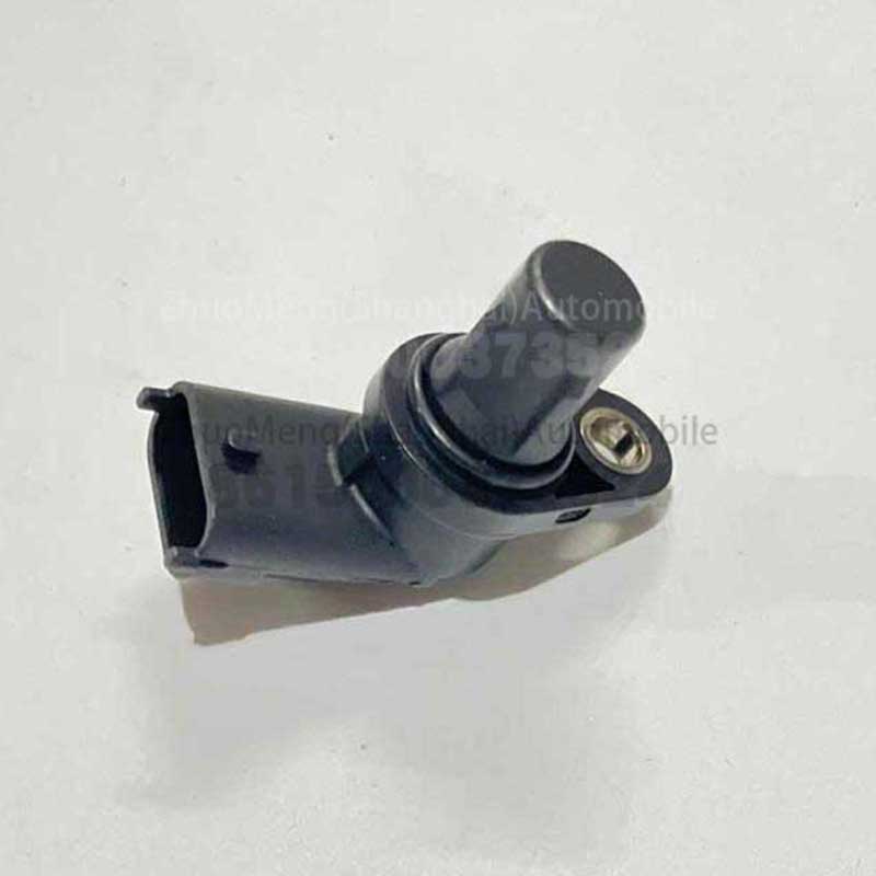
| Products name | Camshaft position sensor |
| Products application | SAIC MAXUS V80 |
| Products OEM NO |
0281002667 |
| Org of place | MADE IN CHINA |
| Brand | CSSOT /RMOEM/ORG/COPY |
| Lead time | Stock,if less 20 PCS,normal one month |
| Payment | TT Deposit |
| Company Brand | CSSOT |
| Application system | Chassis system |
Related products


Product knowledge
Camshaft position sensor is a sensing device, also called synchronous signal sensor, it is a cylinder discrimination positioning device, input camshaft position signal to ECU, is the ignition control signal.
1, function and type Camshaft Position Sensor (CPS), its function is to collect the Camshaft moving Angle signal, and input electronic control unit (ECU), in order to determine the ignition time and fuel injection time. Camshaft Position Sensor (CPS) is also known as Cylinder Identification Sensor (CIS), in order to distinguish from crankshaft Position Sensor (CPS), Camshaft position sensors are generally represented by CIS. The function of the camshaft position sensor is to collect the position signal of the gas distribution camshaft and input it to THE ECU, so that the ECU can identify the compression top dead center of cylinder 1, so as to carry out sequential fuel injection control, ignition time control and deignition control. In addition, the camshaft position signal is also used to identify the first ignition moment during engine starting. Because the camshaft position sensor can identify which cylinder piston is about to reach TDC, it is called the cylinder recognition sensor.photoelectricStructural characteristics ofPhotoelectric crankshaft and camshaft position sensor produced by Nissan company is improved from the distributor, mainly by the signal disk (signal rotor), signal generator, distribution appliances, sensor housing and wire harness plug.The signal disk is the signal rotor of the sensor, which is pressed on the sensor shaft. In the position near the edge of the signal plate to make a uniform interval radian inside and outside two circles of light holes. Among them, the outer ring is made with 360 transparent holes (gaps), and the interval radian is 1. (Transparent hole accounted for 0.5. , shading hole accounted for 0.5.) , used to generate crankshaft rotation and speed signal; There are 6 clear holes (rectangular L) in the inner ring, with an interval of 60 radians. , is used to generate TDC signal of each cylinder, among which there is a rectangle with a wide edge slightly longer for generating TDC signal of cylinder 1.The signal generator is fixed on the sensor housing, which is composed of Ne signal (speed and Angle signal) generator, G signal (top dead center signal) generator and signal processing circuit. Ne signal and G signal generator are composed of a light emitting diode (LED) and a photosensitive transistor (or photosensitive diode), two LED directly facing the two photosensitive transistors respectively.The working principle ofThe signal disc is mounted between a light-emitting diode (LED) and a photosensitive transistor (or photodiode). When the light transmittance hole on the signal disk rotates between LED and photosensitive transistor, the light emitted by LED will illuminate the photosensitive transistor, at this time the photosensitive transistor is on, its collector output low level (0.1 ~ O. 3V); When the shading part of the signal disk rotates between LED and the photosensitive transistor, the light emitted by THE LED can not illuminate the photosensitive transistor, at this time the photosensitive transistor cut off, its collector output high level (4.8 ~ 5.2V).If the signal disk continues to rotate, the transmittance hole and the shading part will alternately turn the LED to transmittance or shading, and the photosensitive transistor collector will alternately output high and low levels. When the sensor axis with the crankshaft and camshaft rotates with, signal light hole on the plate and shading part between the LED and the photosensitive transistor turns, LED light signal plate of pervious to light and shading effect will alternate irradiation to the signal generator of photosensitive transistor, the sensor signal is produced and the crankshaft and camshaft position corresponding to the pulse signal.Since the crankshaft rotates twice, the sensor shaft rotates the signal once, so the G signal sensor will generate six pulses. Ne signal sensor will generate 360 pulse signals. Because the radian interval of the light transmitting hole of G signal is 60. And 120 per rotation of the crankshaft. It produces an impulse signal, so the G signal is usually called 120. The signal. Design installation guarantee 120. Signal 70 before TDC. (BTDC70. , and the signal generated by the transparent hole with a slightly longer rectangular width corresponds to 70 before the top dead center of engine cylinder 1. So that ECU can control the injection advance Angle and ignition advance Angle. Because Ne signal transmittance hole interval radian is 1. (Transparent hole accounted for 0.5. , shading hole accounted for 0.5.) , so in each pulse cycle, the high level and the low level account for 1 respectively. Crankshaft rotation, 360 signals indicate crankshaft rotation 720. Each rotation of the crankshaft is 120. , G signal sensor generates one signal, Ne signal sensor generates 60 signals.Magnetic induction typeMagnetic induction position sensor can be divided into Hall type and magnetoelectric type. The former uses hall effect to generate position signal with fixed amplitude, as shown in Figure 1. The latter uses the principle of magnetic induction to generate position signals whose amplitude varies with frequency. Its amplitude varies with the speed from several hundred millivolts to hundreds of volts, and the amplitude varies greatly. The following is a detailed introduction to the working principle of the sensor:The working principle ofThe path through which the magnetic force line passes is the air gap between the permanent magnet N pole and the rotor, the rotor salient tooth, the air gap between the rotor salient tooth and the stator magnetic head, the magnetic head, the magnetic guide plate and the permanent magnet S pole. When the signal rotor rotates, the air gap in the magnetic circuit will change periodically, and the magnetic resistance of the magnetic circuit and the magnetic flux through the signal coil head will change periodically. According to the principle of electromagnetic induction, alternating electromotive force will be induced in the sensing coil.When the signal rotor rotates clockwise, the air gap between the rotor convex teeth and the magnetic head decreases, the magnetic circuit reluctance decreases, the magnetic flux φ increases, the flux change rate increases (dφ/dt>0), and the induced electromotive force E is positive (E>0). When the convex teeth of rotor are close to the edge of magnetic head, the magnetic flux φ increases sharply, the flux change rate is the largest [D φ/dt=(dφ/dt) Max], and the induced electromotive force E is the highest (E=Emax). After the rotor rotates around the position of point B, although the magnetic flux φ is still increasing, but the rate of change of magnetic flux decreases, so the induced electromotive force E decreases.When the rotor rotates to the center line of the convex tooth and the center line of the magnetic head, although the air gap between the rotor convex tooth and the magnetic head is the smallest, the magnetic resistance of the magnetic circuit is the smallest, and the magnetic flux φ is the largest, but because the magnetic flux can not continue to increase, the rate of change of magnetic flux is zero, so the induced electromotive force E is zero.When the rotor continues to rotate along the clockwise direction and the convex tooth leaves the magnetic head, the air gap between the convex tooth and the magnetic head increases, the magnetic circuit reluctance increases, and the magnetic flux decreases (dφ/dt< 0), so the induced electrodynamic force E is negative. When the convex tooth turns to the edge of leaving the magnetic head, the magnetic flux φ decreases sharply, the flux change rate reaches the negative maximum [D φ/df=-(dφ/dt) Max], and the induced electromotive force E also reaches the negative maximum (E= -emax).Thus it can be seen that every time the signal rotor turns a convex tooth, the sensor coil will produce a periodic alternating electromotive force, that is, the electromotive force appears a maximum and a minimum value, the sensor coil will output a corresponding alternating voltage signal. The outstanding advantage of magnetic induction sensor is that it does not need external power supply, permanent magnet plays the role of converting mechanical energy into electrical energy, and its magnetic energy will not be lost. When the engine speed changes, the rotation speed of the convex teeth of the rotor will change, and the flux change rate in the core will also change. The higher the speed, the greater the flux change rate, the higher the induction electromotive force in the sensor coil.Since the air gap between the rotor convex teeth and the magnetic head directly affects the magnetic resistance of the magnetic circuit and the output voltage of the sensor coil, the air gap between the rotor convex teeth and the magnetic head cannot be changed at will in use. If the air gap changes, it must be adjusted according to the provisions. The air gap is generally designed within the range of 0.2 ~ 0.4mm.2) Jetta, Santana car magnetic induction crankshaft position sensor1) Structure features of crankshaft position sensor: The magnetic induction crankshaft position sensor of Jetta AT, GTX and Santana 2000GSi is installed on the cylinder block near the clutch in the crankcase, which is mainly composed of signal generator and signal rotor.The signal generator is bolted to the engine block and consists of permanent magnets, sensing coils, and wiring harness plugs. The sensing coil is also called the signal coil, and a magnetic head is attached to the permanent magnet. The magnetic head is directly opposite the tooth disk type signal rotor installed on the crankshaft, and the magnetic head is connected with the magnetic yoke (magnetic guide plate) to form a magnetic guide loop.The signal rotor is of toothed disc type, with 58 convex teeth, 57 minor teeth and one major tooth evenly spaced on its circumference. Big tooth is missing output reference signal, corresponding to engine cylinder 1 or cylinder 4 compression TDC before a certain Angle. The radians of the major teeth are equivalent to those of two convex teeth and three minor teeth. Because the signal rotor rotates with the crankshaft, and the crankshaft rotates once(360). , the signal rotor also rotates once (360). , so the crankshaft rotation Angle occupied by convex teeth and tooth defects on the circumference of the signal rotor is 360. , the crankshaft rotation Angle of each convex tooth and small tooth is 3. (58 x 3. 57 x + 3. = 345). , the crankshaft Angle accounted for by major tooth defect is 15. (2 x 3. + 3 x3. = 15). .2) the crankshaft position sensor working condition: when the crankshaft position sensor with the crankshaft rotates, the working principle of the magnetic induction sensor, the signal of rotor each turned a convex tooth, sensing coil will generate a periodic alternating emf (electromotive force in a maximum and a minimum), coil output an alternating voltage signal accordingly. Because the signal rotor is provided with a big tooth to generate the reference signal, so when the big tooth tooth turns the magnetic head, the signal voltage takes a long time, that is, the output signal is a wide pulse signal, which corresponds to a certain Angle before cylinder 1 or cylinder 4 compression TDC. When the electronic control unit (ECU) receives a wide pulse signal, it can know that the top TDC position of cylinder 1 or 4 is coming. As for the coming TDC position of cylinder 1 or 4, it needs to determine according to the signal input from the camshaft position sensor. Since the signal rotor has 58 convex teeth, the sensor coil will generate 58 alternating voltage signals for each revolution of the signal rotor (one revolution of the engine crankshaft).Each time the signal rotor rotates along the engine crankshaft, the sensor coil feeds 58 pulses into the electronic control unit (ECU). Thus, for every 58 signals received by the crankshaft position sensor, the ECU knows that the engine crankshaft has rotated once. If the ECU receives 116000 signals from the crankshaft position sensor within 1min, the ECU can calculate that the crankshaft speed n is 2000(n=116000/58=2000)r/rain; If the ECU receives 290,000 signals per minute from the crankshaft position sensor, the ECU calculates a crank speed of 5000(n= 29000/58 =5000)r/min. In this way, the ECU can calculate the speed of crankshaft rotation based on the number of pulse signals received per minute from the crankshaft position sensor. Engine speed signal and load signal are the most important and basic control signals of electronic control system, ECU can calculate three basic control parameters according to these two signals: basic injection advance Angle (time), basic ignition advance Angle (time) and ignition conduction Angle (ignition coil primary current on time).Jetta AT and GTx, Santana 2000GSi car magnetic induction type crankshaft position sensor signal rotor generated by the signal as the reference signal, ECU control of fuel injection time and ignition time is based on the signal generated by the signal. When the ECu receives the signal generated by the big tooth defect, it controls the ignition time, fuel injection time and the primary current switching time of the ignition coil (i.e. the conduction Angle) according to the small tooth defect signal.3) Toyota car TCCS magnetic induction crankshaft and camshaft position sensorToyota Computer Control System (1FCCS) uses magnetic induction crankshaft and camshaft position sensor modified from distributor, consisting of upper and lower parts. The upper part is divided into detection crankshaft position reference signal (namely cylinder identification and TDC signal, known as G signal) generator; The lower part is divided into crankshaft speed and corner signal (called Ne signal) generator.1) Structure characteristics of Ne signal generator: Ne signal generator is installed below G signal generator, mainly composed of No. 2 signal rotor, Ne sensor coil and magnetic head. The signal rotor is fixed on the sensor shaft, the sensor shaft is driven by the gas distribution camshaft, the upper end of the shaft is equipped with a fire head, the rotor has 24 convex teeth. The sensing coil and magnetic head are fixed in the sensor housing, and the magnetic head is fixed in the sensing coil.2) speed and Angle signal generation principle and control process: when the engine crankshaft, valve camshaft sensor signals, then drive the rotor rotation, the rotor protruding teeth and air gap between the magnetic head change alternately, sensing coil in the magnetic flux change alternately, then the working principle of the magnetic induction sensor shows that in the sensing coil can produce alternating inductive electromotive force. Because the signal rotor has 24 convex teeth, the sensor coil will produce 24 alternating signals when the rotor rotates once. Each revolution of the sensor shaft (360). This is equivalent to two revolutions of the engine crankshaft (720). , so an alternating signal (i.e. a signal period) is equivalent to a crank rotation of 30. (720. Present 24 = 30). , is equivalent to the rotation of the fire head 15. (30. Present 2 = 15). . When ECU receives 24 signals from Ne signal generator, it can be known that the crankshaft rotates twice and the ignition head rotates once. ECU internal program can calculate and determine engine crankshaft speed and ignition head speed according to the time of each Ne signal cycle. In order to accurately control the ignition advance Angle and fuel injection advance Angle, the crankshaft Angle occupied by each signal cycle (30. The corners are smaller. It is very convenient to accomplish this task by microcomputer, and the frequency divider will signal each Ne (crank Angle 30). It is equally divided into 30 pulse signals, and each pulse signal is equivalent to the crank Angle 1. (30. Present 30 = 1). . If each Ne signal is equally divided into 60 pulse signals, each pulse signal corresponds to the crankshaft Angle of 0.5. (30. ÷60= 0.5. . The specific setting is determined by the Angle precision requirements and program design.3) Structure characteristics of G signal generator: G signal generator is used to detect the position of piston top dead center (TDC) and identify which cylinder is about to reach TDC position and other reference signals. So G signal generator is also called cylinder recognition and top dead center signal generator or reference signal generator. G signal generator consists of No. 1 signal rotor, sensing coil G1, G2 and magnetic head, etc. The signal rotor has two flanges and is fixed on the sensor shaft. Sensor coils G1 and G2 are separated by 180 degrees. Mounting, the G1 coil produces a signal corresponding to the engine sixth cylinder compression top dead center 10. The signal generated by G2 coil corresponds to lO before the compression TDC of the first cylinder of the engine.4) Cylinder identification and top dead center signal generation principle and control process: the working principle of G signal generator is the same as that of Ne signal generator. When the engine camshaft drives the sensor shaft to rotate, the flange of the G signal rotor (No. 1 signal rotor) passes through the magnetic head of the sensing coil alternately, and the air gap between the rotor flange and the magnetic head changes alternately, and the alternating electromotive force signal will be induced in the sensing coil Gl and G2. When the flange part of G signal rotor is close to the magnetic head of sensing coil G1, a positive pulse signal is generated in sensing coil G1, which is called G1 signal, because the air gap between the flange and the magnetic head decreases, the magnetic flux increases and the magnetic flux change rate is positive. When the flange part of G signal rotor is close to the sensing coil G2, the air gap between the flange and the magnetic head decreases and the magnetic flux increases

FAQ
1. What’s the Warranty & After-sales?
For OEM/ORG products for auto parts ,we can supply you one year warranty ,you can rest assure to buy and sell it in your place !
For Genuine/Brand(copy) products for auto parts,we can supply you half one year warranty,its cheap and easy accepted by some company,and its quality you can choose different type ,it can last long time to use it ,so rest assure to buy and sell it in your country!
2. Why Choose CSSOT ?
CSSOT ;ZHUO MENG (SHANGHAI)AUTOMOBILE CO.,LTD. What can we do for you ? one company who work with factory directly ,one hand price from ORG /BRAND factory who can give us cheap price ,so you can buy from us and take all spare parts for SAIC MG& MAXUS auto parts ,one company who have many stock for all parts stock and easy took some not stock from our factory . no mater you want OEM or BRAND ,we all can supply you ,you can choose different price and quality from our company .
3.How long is the lead time generally?
First ,if we have stock ,we can send you right away
Second ,if you need more ,some not have stock ,and it depend on your products if common ,if you urgent some parts ,we can help you quickly get what you want
4. How to buy from CSSOT ?
You can buy from us from trade assure order ,TT order,L/C ,and we can keep long term good relationship for business
5. Why i need believe CSSOT ?
Because you can find all from us ,brand parts ,OEM parts from SAIC ,also if you want OE products with your logo for products ,we all can help you !
6. How to find CSSOT parts ?
1. www.saicmgautoparts.com
2. www.buymgautoparts.com
3. www.cssot.en.alibaba.com
4. And some can find from google ,search “mg auto parts “ or “zhuo meng (shanghai) automobile co.,ltd.
7. If you can give us EXW/FOB/CNF/CIF price if we cooperate ?
Of course !
1. if you want EXW price ,then you pay us company account ,and you should help us custom for products !
2. if you want FOB price ,then you pay us company account ,and you should help us custom for products and you tell me which port you may carry and we check all cost and quote you !
3. if you want CNF price ,then you pay us company account , we find shipper and help us our products successful to your port ,without any insurance!
4. if you want CIF price ,then you pay us company account , we find shipper and help us our products successful to your port ,with insurance for products !