The principle of the hinge arrangement of the engine cover is to save space, good concealment, and the hinge is generally arranged in the flow tank. The arrangement position of engine cover hinge needs to be combined with the opening Angle of the engine cover, the ergonomic check of the engine cover and the safety clearance between the surrounding parts. From modeling effect drawing to CAS design, data design, the arrangement of engine cover hinge plays a crucial role.
Hinge position layout design
Considering the convenience of opening the engine cover and the distance from the surrounding parts, the axis is arranged back as far as possible after considering the shape and space restrictions. The two engine cover hinge axes should be in the same straight line, and the left and right hinge arrangements should be symmetrical. Generally, the greater the distance between the two hinges, the better. The function is to increase the engine room space.
Hinge axis design
The closer the hinge axis arrangement is to the outer panel of the engine cover and the rear end of the engine cover seam, the more favorable it is, because the hinge axis is closer to the back, the larger the gap between the engine cover and the fender in the opening process of the engine cover, so as to avoid the interference between the hinge envelope and the envelope of the engine cover body and the peripheral parts in the opening and closing process of the engine cover. However, it is also necessary to consider the installation strength of sheet metal at the hinge of the engine cover, the edge of the engine cover, the electrophoretic performance of sheet metal and the clearance with the surrounding parts. The recommended hinge section is as follows:
L1 t1 + R + b or higher
20 mm or less L2 40 mm or less
Among them:
t1: fender thickness
t2: Thickness of inner plate
R: Distance between hinge shaft center and hinge seat top, recommended ≥15mm
b: Clearance between hinge and fender, recommended ≥3mm
1) The engine cover hinge axis is generally parallel to the Y-axis direction, and the connection between the two hinge axes should be in the same straight line.
2) The gap between engine cover opening 3° and fender plate, ventilation cover plate and front windshield glass is not less than 5mm
3) The outer plate of the engine cover is offset 1.5mm along ±X, ±Y and ±Z, and the opening envelope does not interfere with the fender plate
4) Set the hinge axis position according to the above conditions. If the hinge axis cannot be adjusted, the splinter can be modified.
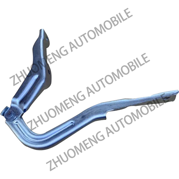
Hinge structure design
Design of hinge base:
On the two hinge pages of the hinge, sufficient contact surface shall be left for the fastening bolt, and the Angle R of the bolt to the surrounding part shall be ≥2.5mm.
If the hinge arrangement of the engine cover is located in the head collision area, the lower base should have a crushing feature. If the hinge arrangement is not related to the head collision, it is not necessary to design the crushing feature to ensure the strength of the hinge base.
In order to increase the strength of hinge base and reduce the weight, according to the specific shape of the base, it is necessary to increase the weight reduction hole and flange structure. In the design of the base, a boss should be designed in the middle of the mounting surface to ensure the electrophoresis of the mounting surface.
Hinge upper seat design:
In order to prevent the hinge in the physical state because of the installation or precision problems lead to interference between the upper and lower hinge, hinge hinge between the upper and lower seat motion envelope clearance, requirements ≥3mm.
To ensure strength, the stiffening flanges and stiffeners need to run through the entire upper seat to ensure that the hinged upper seat can meet the test requirements. A boss should be designed in the middle of the mounting surface to ensure the electrophoresis of the mounting surface.
The hinge mounting hole aperture design should have a certain adjustment margin to meet the engine cover installation and adjustment, the hinge engine cover side and body side mounting holes are designed to be Φ11mm round hole, 11mm×13mm waist hole.
Engine cover hinge opening Angle design
In order to meet the requirements of ergonomics, the opening height of the engine cover assembly should meet the requirements of 95% male head movement space and 5% female hand movement space, that is, the design area composed of 95% male head movement space with front protection and 5% female hand movement space without front protection in the figure.
In order to ensure that the engine cover pole can be removed, the opening Angle of the hinge is generally required to be: the maximum opening Angle of the hinge is not less than the engine cover opening Angle +3°.
Peripheral clearance design
a. The front edge of the engine cover assembly is 5mm without interference;
b. There is no interference between the rotating envelope and the surrounding parts;
c. Engine cover assembly overopened 3° hinge and fender clearance ≥5mm;
d. The engine cover assembly is opened 3° and the clearance between the body and the surrounding parts is more than 8mm;
e. Clearance between hinge mounting bolt and engine cover outer plate ≥10mm.
Method of checking
Engine cover clearance check method
a, the engine cover along the X, Y, Z direction offset ±1.5mm;
B. The offset engine cover data is rotated downward by the hinge axis, and the rotation Angle is 5mm offset at the front edge of the engine cover;
c. Requirements: Clearance between the rotating envelope surface and the surrounding parts is not less than 0mm.
Check method of engine cover opening:
a, the engine cover along the X, Y, Z direction offset ±1.5mm;
B. Over-opening Angle: the maximum opening Angle of the hinge is +3°;
c. Clearance between engine cover hinge over open envelope surface and fender plate ≥5mm;
d. Clearance between the engine cover body over the envelope surface and the surrounding parts is more than 8mm.