1. The utility model relates to the technical field of automobile doors, in particular to a middle sliding door slide rail cover mounting structure.
Background technique:
2. At present, most commercial vehicles or vans are equipped with a middle sliding door, and the sliding rails on the middle sliding door are generally arranged on the outer panel of the side wall of the body. In order to install the middle sliding door slide rail, it is necessary to provide a groove with a length extending in the front and rear direction of the vehicle body on the surface of the body side panel and below the rear side glass, and the middle sliding door sliding rail is arranged in the groove. Since the sliding rail of the middle sliding door is directly exposed to the outer panel of the side wall, it is easy to accumulate dust and be eroded by rain during the use of the vehicle, resulting in the sliding door hinge roller not sliding smoothly, which makes the sliding door close and issue the card. For this reason, a cover is usually used. Plate to cover the slide rail of the middle sliding door to achieve the purpose of hiding the sliding rail of the middle sliding door.
3. However, the existing cover is usually fixed with bolts and nuts to the side panel outer panel. After the cover is fixed, the remaining interior parts are finally installed in the car (the removal method is just the opposite). The cover plate of the slide rail of the middle sliding door is hidden, and it is difficult to be locked and removed during the installation process. Secondly, a reserved cover shape needs to be made on the side wall outer panel. If the cover plate is cancelled, the appearance of the side wall outer panel will be seriously affected and the appearance quality of the whole vehicle will be reduced. At the same time, some models do not need a cover plate, so there is no need to reserve a cover plate shape on the side wall outer plate. As a result, the side wall outer plate has two specifications, which not only increases the cost of opening the side wall outer plate, but also does not Facilitate the management of parts.
Technical implementation elements:
4. In view of the above-mentioned deficiencies of the prior art, the technical problem to be solved by this utility model is: how to provide a middle sliding door slide rail cover plate installation structure to improve the existing cover plate installation process for concealing the middle sliding door slide rails It is more difficult to lock and remove, and it is convenient to switch between whether there is a cover plate, and there is no need to reserve the shape of the cover plate on the side wall outer plate.
5. in order to solve the above-mentioned technical problem, the utility model has adopted the following technical scheme:
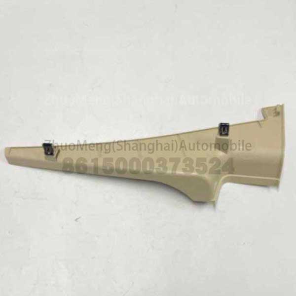
6. A middle sliding door slide rail cover installation structure, comprising a side wall outer plate, a slide rail body horizontally installed on the side wall outer plate, and a cover plate for shielding the slide rail body, along the upper surface of the slide rail body A plurality of clamping blocks are vertically connected at uniform intervals in the length direction, and positioning holes and strip holes are opened on the surface of each clamping block; the cover plate is composed of two sections, the first section of the cover plate has a rectangular shell structure, and the second The segment has a trapezoidal shell-like structure, one end of the first segment of the cover plate is bent inward to form a curved portion, the other end of the first segment of the cover plate is fixedly connected with the second segment of the cover plate, and the inner surface of the first segment of the cover plate is installed with a strip. There are clips corresponding to the positions of the holes one-to-one, and the clips are arranged close to the curved part; a positioning column corresponding to the position of one of the positioning holes is arranged on the inner surface of the first section of the cover plate, and the diameter of the positioning column matches the diameter of the positioning hole and is inserted into the positioning hole , in order to limit the up and down and front and rear movement of the cover plate; a buckle is welded on the surface of the side wall outer plate in the extension direction of the slide rail body, and the cross section of the buckle is a Z-shaped structure, and the inner surface of the second section of the cover plate is provided with a buckle. The position corresponds to the clamping part, and the clamping part is in the shape of an arched plate, so that the second section of the cover plate can be positioned by inserting the clamping part through the buckle.
7. Further, an abutment portion abutting against the surface of the slide rail body is provided at horizontal intervals on the inner surface of the first section of the cover plate.
8. Further, a filler is provided on the inner surface of the second section of the cover plate, so as to keep the second section of the cover plate in close contact with the outer side panel through the filler.
9. Further, the filler is sponge.
10. Further, the first section of the cover plate and the second section of the cover plate are integrally formed by injection molding.
11. Further, the plurality of clamping blocks are located on the same horizontal line, and the position of the buckle is lower than the horizontal line.
12. Further, chamfer the end of the positioning column away from the cover plate to form a guide cone.
13. Compared with the prior art, the beneficial effects of the present utility model are:
14.1. In the present invention, the cover plate and the side wall outer plate are fixed by the clamping method, which changes the fixing method of the existing cover plate, and at the same time does not need to reserve the shape of the cover plate on the side wall outer plate. When installing, insert the clips on the outer panel of the side panel into the clamping part. After the clamping is in place, the positioning column will keep facing the positioning hole. Press the cover plate to make the clips fit into the strip holes, and the cover plate and the outer panel of the side panel will be completed. The plate is fixed, which reduces the difficulty of installation. When dismantling, the cover plate is pulled to disengage the clip from the strip hole, that is, the dismantling of the cover plate is completed, and the cover plate removal is convenient.
15.2. One of the clips (buckles) used for the installation of the cover plate of the present invention is arranged on the side wall outer plate, and the rest are arranged on the sliding rails. When the cover plate is not required to be installed, the side wall outer plate and the sliding rail are cancelled. It is convenient to switch between with and without a cover plate, and it is not necessary to separately design the side wall outer plate when there is a cover plate, which reduces the manufacturing cost of the side wall outer plate.
Description of drawings
16. In order to make the purpose, technical scheme and advantages of the utility model clearer, the utility model will be described in further detail below in conjunction with the accompanying drawings, wherein:
17. Figure 1 is a schematic diagram of the overall structure of the present utility model;
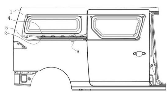
18. Figure 2 is a schematic diagram after the cover plate is removed in Figure 1;
19. Figure 3 is an enlarged schematic view of a place in Figure 2;
20. Figure 4 is a schematic structural diagram of a cover plate in the utility model.
21. In the figure: side wall outer plate 1, slide rail body 2, cover plate 3, clamping block 4, bending part 31, clamp 32, positioning column 33, clamping part 34, abutting part 35, positioning hole 41, strip Shaped hole 42 , buckle 5 .
Detailed ways
22. The present utility model will be further described in detail below in conjunction with the accompanying drawings.
23. As shown in Figures 1 to 4, a middle sliding door slide rail cover installation structure in this specific embodiment includes a side wall outer plate 1 and a slide rail body 2 horizontally installed on the side wall outer plate, and a cover plate 3 for shielding the slide rail body, a plurality of clamping blocks 4 are vertically connected on the upper surface of the sliding rail body at even intervals along its length direction, and the surface of each clamping block is provided with a positioning hole 41 and a strip hole 42; The plate 3 is composed of two sections. The first section of the cover plate has a rectangular shell-like structure, and the second section of the cover plate has a trapezoidal shell-like structure. One end of the first section of the cover plate is bent inward to form a curved portion 31 to bend the slide rail body. The other end of the first section of the cover plate is fixedly connected to the second section of the cover plate, and the inner surface of the first section of the cover plate is installed with clips 32 corresponding to the positions of the strip holes 42 one-to-one, and the clips are arranged close to the curved part. The y-direction freedom of the cover (that is, the width of the vehicle body) is limited by the clips on the cover being snapped into the strip holes. In order to limit the x-direction freedom of the cover plate (that is, the front-rear direction of the vehicle body) and the z-direction degree of freedom (that is, the up and down direction of the vehicle body), a positioning column 33 corresponding to the position of one of the positioning holes is provided on the inner surface of the first section of the cover plate. The diameter of the column matches the diameter of the positioning hole and is inserted into the positioning hole to limit the x-direction freedom and z-direction freedom of the cover plate. A buckle 5 is welded on the surface of the side wall outer plate 1 in the extending direction of the body of the slide rail. The cross-section of the buckle is in a Z-shaped structure. The inner surface of the second section of the cover plate is provided with a buckle portion 34 corresponding to the position of the buckle. , the clamping part is in the shape of an arched plate, so that the second segment of the cover plate can be positioned in the x-direction by inserting the clamping part into the clamping part.
24. In the present utility model, the cover plate and the side wall outer plate are fixed by means of snap connection, which changes the fixing of the existing cover plate.
It is not necessary to reserve the shape of the cover plate on the outer panel of the side wall. When installing, insert the clips on the outer panel of the side panel into the clamping part. After the clamping is in place, the positioning column will keep facing the positioning hole. Press the cover plate to make the clips fit into the strip holes, and the cover plate and the outer panel of the side panel will be completed. The plate is fixed, which reduces the difficulty of installation. When dismantling, the cover plate is pulled to disengage the clip from the strip hole, that is, the dismantling of the cover plate is completed, and the cover plate removal is convenient.
25. Set the buckle on the side panel outer panel and the clamping block on the slide rail. When you do not need to install the cover plate, you can cancel the clamping block buckle on the side panel outer panel and the slide rail, which is convenient for whether there is a cover or not. Switching between panels eliminates the need to separately design the side panel outer panel when there is a cover plate, thereby reducing the manufacturing cost of the side panel outer panel.
26. Specifically, the first section of the cover plate and the second section of the cover plate are integrally formed by injection molding.
27. In order to facilitate the insertion of the positioning column 33 into the positioning hole 41, the end of the positioning column away from the cover plate is chamfered to form a guide cone.
28. Referring to Figure 4, after the cover plate 3 is fixed to cover the slide rail body 2 by means of clamping, in order to ensure the stability of the cover plate when it is clamped and not loose The abutting portion 35 abutting against the surface of the slide rail body. In this way, the abutting portion abuts the surface of the middle slide rail during installation, so as to ensure the stability of the cover plate when it is clamped.
29. Referring to Figure 2, in order to further ensure the stability of the cover plate when it is clamped, a plurality of clamping blocks 4 are located on the same horizontal line, and the position of the buckle 5 on the side wall outer plate 1 is lower than the horizontal line. In this way, the first section of the cover plate and the sliding rail body snap joint, and the second section of the cover plate and the insertion point of the side wall outer plate are misaligned with each other, and the snap-fit installation of the cover plate is more stable.
30. In order to ensure the close contact between the second section of the cover plate and the outer panel of the side wall, the utility model is also provided with a filler on the inner surface of the second section of the cover plate, so as to keep the second section of the cover plate and the outer panel of the side wall tightly through the filler. paste to avoid gaps between the two. The filler can be foam, sponge, or the like.
31. Finally, it should be noted that the above embodiments are only used to illustrate the technical solutions of the present utility model and are not intended to be limiting. Although the present utility model has been described with reference to the preferred embodiments of the present utility model, those of ordinary skill in the art should It will be understood that various changes in form and details may be made therein without departing from the spirit and scope of the present invention as defined by the appended claims.